Twin trucker CB antennas for 27MHz are reminiscent of the 70’s and particularly North American trucks as seen on those in the movie Smokey and the Bandit. As reported in another article, this type of installation appears to be the order of the day for New Zealand trucks fitted with 26MHz CB radio. In Australia, we haven’t seen this configuration for quite some time, decades in fact. Back in the day, International trucks, particularly the ACCO 3070 were mostly fitted with this type of antenna configuration so presumably, they were available as a dealer fitted option. So let’s take a trip down memory lane to recall the configuration, understand what this configuration was designed to achieve, how they were set up and tuned.
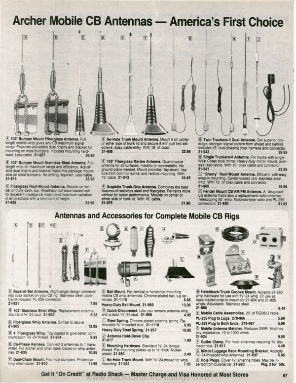
Back in the 1970’s, Twin trucker antennas were typically “Archer” brand sold by Tandy Electronics. The catalogue number of the kit was #21-942 and came with two antennas complete with co-phasing harness. The brand of antenna is not important, but what is important is that both antennas are of the same brand and model. In the case of trucks in New Zealand, GME Electrophone antennas were most common. The idea of this configuration came about in an effort to try and solve the problem of antenna radiation pattern distortion caused by large metal pantecnicon trailers.
This type of antenna system generally comes under the category of “driven array” since both antennas are driven by the CB radio transmitter. Now, this is where it gets interesting because depending upon how far apart they are spaced and the harness configuration will determine the final radiation pattern of the system.
The resulting radiation pattern is bi-directional like a dipole. So, in terms of how we set up the co-phasing harness, the three possible configurations (and radiation patterns) are:
- “Broadside Array” – This is the usual case for truck installations and ideally requires that the antennas be half a wave apart (3.6m) and that the Tee in the coax harness be located in the centre, ie 1.8m out to each antenna. In theory, when mounted on the mirror frames on a yesteryear truck you will be absolutely battling to realise a quarter wave spacing (102”) since trucks are a maximum of 2.4m or 8’ wide. Each mirror mount bracket would need to be on the absolute outside perimeter of the mirror frame to achieve the 102” spread. As we will see later, the physical spacing between the antennas also has a final effect on the final radiation pattern. The main radiation is to the front and rear of the vehicle which suits truck drivers as they travel along the highways.
- “End-Fire Array” – This is achieved by adding an additional half wavelength of coax onto one of the antennas. If the desired radiation pattern was also to be to the front and rear of the vehicle, the antennas would also have to be mounted at the front and rear (ie opposite that above).
- “Beam Pattern” – if instead of adding another half wave of coax onto one antenna, we make it just a quarter wave length, the resulting pattern is essentially that of a two element yagi. Imagine driving around with a two element yagi at 27MHz mounted on your vehicle!!! If the desired direction of the bulk of the radiation pattern was to be mostly forward with less to the rear, the antenna with the shorter coax goes to the front of the vehicle and that with the longer coax goes to the rear.
With regards to the phasing harness itself the velocity factor of the coaxial cable has to be taken into account. Further, we are using two nominally 50 Ohm antennas and we require a 50 Ohm impedance at the radio’s antenna socket. To this end, we need to do some antenna matching – ie make each antenna leg look like 100 Ohms because two lots of this in parallel gives 50 Ohms. This is achieved by using two pieces of 75 Ohm coaxial cable (RG59 or RG11), each three quarters of a wavelength long taking the velocity factor into account.
Commercially made co-phasing harnesses must not be cut. If you have a look at the advertising brochure, the middle of the harness is the PL259 plug itself that goes to the radio. While this method is cheaper, it will make tuning the antennas for best VSWR (not) fun. As the antennas will react with each other during adjustment, the easiest way would be to make a testing harness (getting each ¾ Wave leg the correct length of course). In particular, we need one of the legs fitted with the same socket as that on the back of the radio so that a dummy load can be connected to it. The tuning process would be to terminate one ¾ wave leg with the dummy load while we tune the antenna on the other leg for best VSWR. Once we are happy with that one, we swap the connections around so that the other antenna can be tuned. On that note, if one antenna in the future became damaged because it got wacked on an obstacle, the resulting VSWR of the array could be high – high enough to damage the radio’s final transistors in the transmitter. So as you can see, it is a lot of effort to go through for a small amount of improvement.

